
BSC (HONS) ENGINEERING
(ELECTRICAL AND ELECTRONIC)
LEVEL FOUR
SIGNAL AND CIRCUIT ANALYSIS TECHNIQUES
4EJ520
Table of Contents
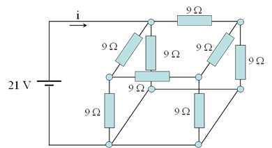
- Simplify the circuit shown in figure 1 and then calculate the total current ‘I’ from the simplified version. 3
- Simulate the original and simplified circuits on OrCAD (PSPICE) and comment on your simulation results 6
- Replace the 21V DC source in figure 1 with 50V AC (rms) and comment on your simulation results 8
- Replace each of the resistors in figure 1 with a 10µF capacitor, and use AC source at different frequency range (say 50, 500, and 5k Hz). Comment on your simulation results 9
- Replace each of the resistors in figure 1 with a 2mH inductor, and use AC source at different frequency range (say 50, 500, and 5k Hz). Comment on your simulation results. 12
- Calculate ix (t) and vL(t) in the circuit shown in figure 2 bellow 16
- Simulate the circuit in figure 2 to verify your calculated results in part ‘f’. 18
a. Calculation of I in the below: –
Answer: –
In an electrical circuit the resistors play an important role. Resistors can be connected serially one after another or parallelly one across another or combination. There is various technique to obtain equivalent resistance of combination of series and parallel circuits. The cube in the above figure has 12 edges and its equivalent resistance can be calculated with the number of nodes in series and parallel.
Formulas: –
Resistance when connected(serially) = R1 + R2 +R3 etc
Resistance when connected (Parallel) = 1/R1 +1/R2 + 1/R3
Below is cubical form of resistors can be simplified.